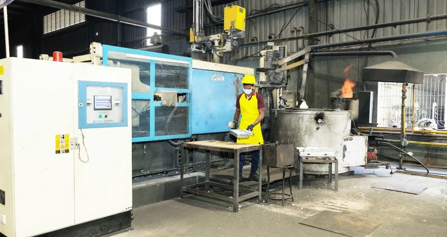
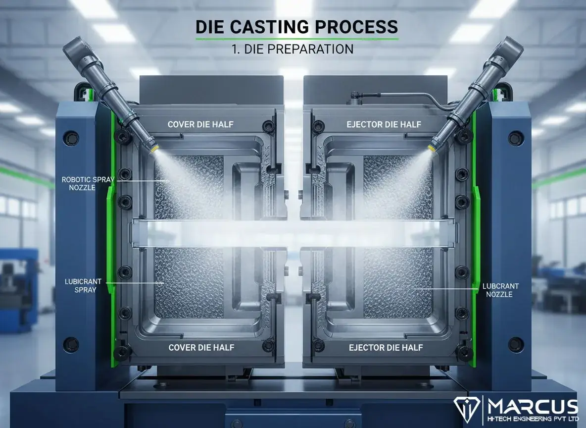
One Pour, One Perfect Part: The Die Casting Process Explained
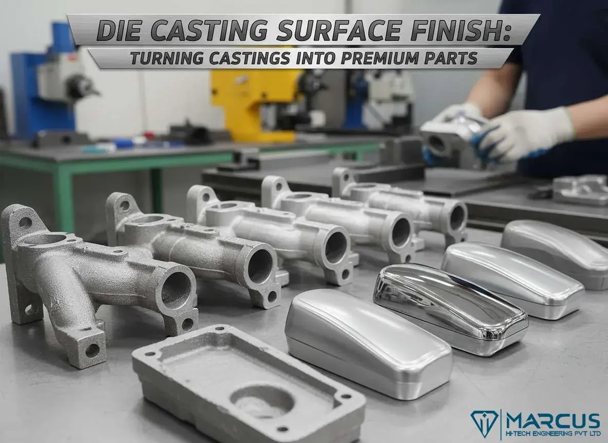
Die casting surface finishing transforms raw aluminum castings into high-performance components with improved durability pro
Read article →

Die casting molds are precision instruments—complex assemblies of hardened steel that must withstand extreme temperatures, crushing pressures, and hundreds of thousands of cycles. Understanding mold anatomy and design principles is essential for engineers specifying die cast parts.
The cavity forms the part’s exterior surfaces while cores create internal features. Together, they define every detail of your component. These are machined into hardened tool steel (typically H13 or P20) to withstand thermal and mechanical stress.
The cavity is the hollow space within the mold, essentially the negative impression of the final part’s exterior. Precision in cavity design directly translates to part accuracy.
Every die splits into at least two halves:
The fixed half typically contains the sprue—where molten metal enters the die. The moving half houses the ejection system that pushes finished parts from the mold.
The gating system controls how molten metal flows into the cavity:
Runner System: Channels that distribute metal from the sprue to one or multiple cavities. Proper runner design ensures smooth, turbulence-free flow.
Gates: Connection points between runners and part cavity. Gate design critically affects:
Common gate types include edge gates, submarine gates, and spoke gates. Size and location depend on part geometry, wall thickness, and alloy properties.
Overflow Wells: Reservoirs that capture initial metal flow, gases, and impurities before they contaminate the part. Overflows also provide back-pressure that helps fill thin sections.
After solidification, parts must be forcefully removed from the mold. The ejection system includes:
Ejector Pins: Push against the casting to break it free. Strategic placement is critical—pins must distribute force evenly without damaging the part. Pin locations typically become visible marks on finished parts, so they’re positioned on non-cosmetic surfaces.
Ejector Plate: Drives all ejector pins forward simultaneously when the die opens.
Return Pins: Pull ejector pins back to their starting position as the die closes.
Proper ejection design prevents:
Undercuts and features perpendicular to the draw direction require slides or core pulls—movable mold components that retract before part ejection.
Slides are wedge-driven mechanisms that move laterally as the die opens. An angled surface (wear plate) cams the slide outward, retracting the core before ejection begins.
Design Considerations:
Try to avoid using sliders with long travel distances in your design, as they can wear out the mold faster. If you must use them, adding guide rails will help the slider move smoothly and last longer.
Every slide increases cost and maintenance. Design strategies to reduce slides:
Cooling system design dramatically impacts cycle time, part quality, and tool life. Properly designed cooling channels are placed to distribute cooling evenly across the mold, preventing hot spots that could cause warping or uneven solidification.
The die acts as a massive heat sink, extracting thermal energy from molten metal. But cooling must be controlled:
Placement: Position cooling channels to extract heat evenly. For instance, closely spaced channels around thick sections stabilize temperature and prevent hot spots.
Spacing: Aim for cooling channels spaced 0.5-1 inch apart, optimizing heat transfer to reduce cycle times.
Flow Rate: Adequate water flow rates ensure consistent temperature control throughout the cycle.
Temperature Differential: Maintaining the correct temperature differential between inlet and outlet prevents thermal shock and extends tool life.
Conformal Cooling: Channels that follow part contours for uniform temperature distribution. Often requires additive manufacturing to create complex channel geometries.
Baffle and Bubbler Systems: Used in cores and deep pockets where conventional straight-line channels can’t reach.
Temperature Control Units: Circulate water (or oil for high-temperature applications) at precise temperatures to maintain optimal die temperature.
They significantly influence cycle time; efficient cooling means the part solidifies faster, so the mold can be opened sooner, increasing production speed.
As molten metal fills the cavity at high speed, air must escape. Without proper venting, trapped air compresses, creating defects.
Air trapped in the cavity causes:
Vents are small, intentional escape pathways in the mold that allow gases to exit the cavity as it fills with metal. Without proper venting, trapped air in the cavity would compress and form gas porosity or cause incomplete filling and surface defects in the casting.
Vent Locations: Typically at the far end of metal flow—opposite the gates—and along parting lines where air naturally collects.
Vent Dimensions: Must be large enough to evacuate air quickly but small enough that molten metal doesn’t escape. Typical vent depths: 0.025-0.075mm.
Overflow Integration: Overflow wells serve double duty—they capture impurities and provide venting space for expelled gases.
Some molds include overflow wells or vent plugs in deep areas to help capture expelled air and any impurity or oxide skins carried with the flow.
For critical applications, vacuum systems evacuate air from the cavity before injection:
Die casting dies endure brutal conditions: molten aluminum at 700°C, injection pressures exceeding 10,000 PSI, and thermal cycling thousands of times per day.
H13: The industry standard for aluminum die casting. Excellent hot hardness, thermal fatigue resistance, and toughness. Typical hardness: 44-48 HRC.
P20: Used for less demanding applications or prototype tooling. Lower cost than H13 but reduced thermal performance.
Specialized Coatings: PVD coatings, nitriding, or other surface treatments improve wear resistance, reduce soldering, and extend tool life.
Standard lifespan depends on alloy and conditions:
Effective cooling systems and consistent maintenance procedures, including polishing, inspection, and re-coating, contribute to the longevity of dies and minimize casting defects.
Modern mold design relies heavily on simulation software to predict and prevent problems before cutting steel.
Flow Analysis: Visualizes how molten metal fills the cavity, revealing turbulence, air traps, and cold spots.
Thermal Analysis: Predicts cooling patterns, hot spots, and solidification sequence.
Stress Analysis: Identifies areas of high stress that may crack during cooling or ejection.
Optimization: Allows engineers to test gate locations, adjust cooling channels, and refine venting without expensive trial-and-error.
By following this process, manufacturers create molds that are efficient, durable, and defect-free.
Die casting tooling is both art and science. The mold determines part quality, production efficiency, and ultimately profitability. Understanding these fundamentals helps engineers design better parts, specify appropriate tooling, and work more effectively with their die casting partners.
Investment in proper tool design pays dividends throughout the production run. A well-designed die produces consistent, defect-free parts for hundreds of thousands of cycles. A poorly designed die creates constant headaches—and costs that quickly exceed any initial savings.
More process, tooling, and sourcing notes from the Marcus engineering team.
Die casting surface finishing transforms raw aluminum castings into high-performance components with improved durability pro
Read article →Explore die casting surface finish options. From powder coating to anodizing, learn how to protect and enhance your metal parts.
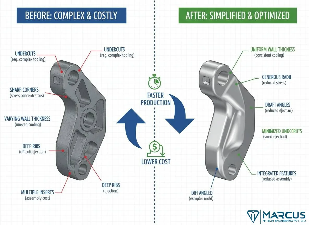
Read article →Master DFM engineering for die casting. Learn how optimized wall thickness and draft angles slash manufacturing costs.
Read article →